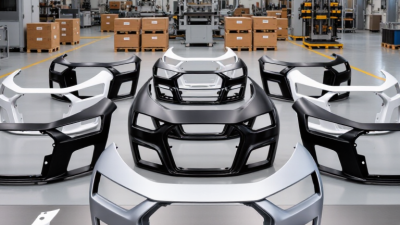
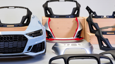
An Audi Bumper is more than a painted cover at the front or rear of the vehicle. It forms part of the car’s impact-management system, working with energy absorbers, reinforcement beams, crash sensors, and mounting brackets. During a low-speed collision, the outer cover may flex or crack while the absorber beneath helps reduce transferred force. The design also supports airflow, pedestrian protection features, parking sensors, cameras, and lighting components on certain Audi models.
Small details matter. A bumper may look intact, yet hidden brackets can be bent behind the grille. A loose sensor can trigger warning messages, while an uneven panel gap may reveal deeper damage. Professional inspection should therefore include the cover, absorber, reinforcement bar, sensor mounts, wiring, and nearby cooling components. Audi’s repair information and model-specific procedures remain important because bumper construction varies between generations and trim levels.
The material is not always obvious.
Some covers use flexible plastic, while internal parts provide much greater structural support. Replacing only the visible shell may not restore proper protection or sensor operation. Calibration can also be required after impact-related repairs, especially when radar or camera systems are involved. This is where practical experience becomes valuable, although even experienced technicians can miss concealed damage without proper testing. A reliable assessment combines visual checks, scan-tool results, manufacturer guidance, and careful road-safety judgment. Understanding how an Audi Bumper works helps owners recognize repair risks, ask better questions, and avoid treating cosmetic damage as the whole problem.
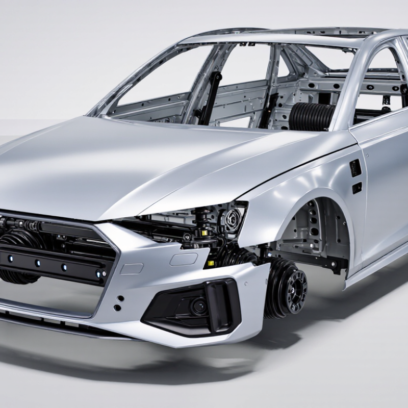
A vehicle bumper is not one solid shell. It is a coordinated structure with several working layers. The fascia is the painted outer cover that shapes airflow and protects the parts behind it. It may flex during a light contact, but it is not the main crash-strength component.
Small gaps matter. Uneven spacing can reveal damaged brackets or hidden deformation.
Behind the fascia, a rigid beam spreads impact energy across the vehicle’s frame. The absorber, often made from energy-absorbing foam or molded plastic, reduces force before it reaches the beam. Some designs include parking sensors, radar units, wiring, and mounting clips inside the bumper assembly. These sensors need precise alignment. A slightly tilted sensor can create false warnings or miss an obstacle.
In repair work, I have seen a clean-looking fascia hiding a cracked absorber and bent reinforcement beam. That is why visual inspection alone is unreliable. The bumper should be removed when impact damage seems deeper than surface marks.
Technicians should also check sensor brackets, wiring connectors, and calibration requirements. Not every replacement part fits perfectly, even when it appears correct. Confirming measurements and fastener positions prevents later rattles, warning lights, and uneven panel gaps.
A vehicle bumper is more than a painted outer cover. It includes an absorber, reinforcement beam, brackets, and mounting points. During a low-speed collision, these parts spread force across a wider area. The bumper does not remove impact energy. Instead, it slows and redirects that energy. This helps reduce concentrated damage near lamps, cooling components, and body panels.
In a 2.5-mph FMVSS 581 test, the vehicle contacts a fixed barrier at a controlled speed. Inspectors then check visible and functional damage. The cover may flex, while foam or a crushable absorber compresses behind it. The reinforcement beam distributes force toward the mounts. The mounts may deform slightly, extending the stopping distance. That small delay matters. Test results can change with temperature, impact angle, tire condition, or previous repairs. Real-world crashes are less predictable. No bumper works perfectly.
Tips: After a minor impact, inspect panel gaps, fasteners, sensors, and lamp alignment. A small crack can hide a displaced absorber. Pressing the cover back into shape may look acceptable, but it can weaken future protection. Use the correct replacement parts and verified torque settings. Photograph damage before disassembly. In practical inspections, overlooked brackets often explain later rattles or uneven gaps. The lesson is useful, though not absolute: appearance alone cannot prove structural condition.
At the 2.5 mph impact speed used in FMVSS 581 bumper testing, the kinetic energy that must be managed depends primarily on vehicle mass. The chart shows the calculated impact energy for representative vehicle masses. A bumper system distributes this energy through controlled deformation, impact absorbers, mounts, and the surrounding structure to reduce concentrated damage.
Values are calculated using the kinetic-energy equation E = ½mv², with 2.5 mph converted to 1.1176 m/s. Actual energy distribution varies with vehicle design, impact alignment, and test conditions.
A modern passenger-vehicle bumper is a layered energy-management system, not a single plastic shell. The visible fascia usually uses PP/EPDM, a flexible polypropylene blend that resists cracking, minor impacts, and temperature changes. Behind it sits foam or molded absorption material, followed by a reinforcement beam. The fascia hides the engineering. During a low-speed impact, it spreads contact across a wider area. The absorber then compresses, while the beam limits intrusion toward the body structure.
Material selection balances weight, flexibility, strength, and repairability. PlasticsEurope eco-profile data places polypropylene density near 0.9 g/cm³, supporting lightweight fascia design. However, density alone does not predict real-world durability. Weathering, paint adhesion, fasteners, and repeated impacts can change performance. Small design details matter.
The reinforcement beam typically uses high-strength steel or aluminum. WorldAutoSteel’s Advanced High-Strength Steel Application Guidelines define advanced grades from approximately 550 MPa tensile strength upward, with some grades exceeding 1,000 MPa. These values help the beam resist bending and distribute impact loads into the crash boxes. U.S. NHTSA Part 581 evaluates 5-mph front and rear impacts, plus 2.5-mph corner impacts. That standard is useful, but it does not guarantee cosmetic survival in every collision. Real repairs still require careful inspection. A slightly bent beam may look harmless. It may not be.
A vehicle bumper is more than a painted outer shell. It combines flexible covers, energy-absorbing foam, reinforcement beams, and electronic sensors. Behind the surface, radar, ultrasonic, and impact sensors monitor nearby objects and sudden changes in movement. Their positions matter. Even a small shift can affect detection accuracy.
During a collision, impact sensors send rapid signals to the restraint control module. The module compares crash force, direction, speed, and occupant information. It then decides whether airbags and seat-belt pretensioners should activate. The bumper does not trigger airbags by itself. It provides a critical sensing area within a larger safety system. Timing is extremely precise.
ADAS sensors support automatic emergency braking, parking assistance, blind-spot alerts, and adaptive cruise functions. Dirt, ice, paint buildup, or a slightly bent bumper can weaken their performance. After a low-speed impact, a bumper may look fine but hide a cracked bracket or displaced radar unit. Workshop inspections should include diagnostic scans, wiring checks, and sensor calibration. A road test alone is not enough. In practice, repairs sometimes focus too heavily on appearance. That is a mistake worth reconsidering. Reliable operation depends on correct mounting, clean sensor surfaces, approved parts, and calibration procedures suited to the vehicle.
What Is an Audi Bumper and How Does It Work?
An Audi bumper is an energy-management system, not merely a painted cover. It includes the fascia, absorber, reinforcement beam, brackets, sensors, and attachment points. During a low-speed collision, the outer cover spreads contact. The absorber then compresses, reducing force transferred to the vehicle structure. UNECE Regulation No. 42 specifies low-speed bumper impact procedures that can include a 4 km/h test speed. This check examines deformation, detachment, and recovery after impact. It does not prove every hidden component remains safe.
OEM repair standards require technicians to follow the vehicle-specific repair manual. They should record the impact direction, replace damaged retainers, and inspect the reinforcement beam carefully. Heat reshaping may weaken plastic, if the manual prohibits it. Post-repair scanning is also important when radar, parking sensors, or cameras sit behind the bumper. NHTSA reported 5.93 million police-reported crashes in 2022, showing why consistent repair control matters. A 4 km/h check can expose poor fitment, but it cannot replace sensor calibration or structural measurement. A visual pass can feel convincing. It can still be wrong. Industry repair data also shows a practical problem: modern bumper work often involves electronic systems, not only paint and plastic. Technicians should photograph damaged clips and measure panel gaps before delivery.
| System or Check Area | Typical Component or Requirement | How It Works or Is Checked | Repair or Inspection Standard |
|---|---|---|---|
| Outer bumper cover | Molded thermoplastic fascia, commonly marked with a polymer identification code | Provides the visible aerodynamic surface and distributes minor contact loads over a wider area. | Verify cracks, tears, deformation, mounting damage, paint adhesion, and correct material-specific repair limits before refinishing or replacing. |
| Energy absorber | Foam or molded energy-absorbing element positioned behind the cover | Compresses or crushes during a low-speed impact to reduce the force transferred to the reinforcement structure. | Replace when crushed, permanently deformed, split, contaminated, or otherwise outside the vehicle maker’s approved reuse criteria. |
| Reinforcement beam | High-strength steel or aluminum cross-car beam, depending on vehicle design | Spreads impact energy across the front or rear structure and helps protect the passenger compartment in appropriate crash conditions. | Measure for bending, buckling, cracking, and attachment damage. Do not straighten or heat-strengthened material unless an approved procedure specifically permits it. |
| Crash boxes and mounting points | Replaceable deformation members and bolted attachment points between the beam and body structure | Controlled deformation absorbs energy before it reaches the main body structure. | Check bolt holes, flanges, alignment, fasteners, and deformation marks. Damaged deformation members normally require replacement rather than reshaping. |
| Parking sensors and radar areas | Ultrasonic sensors, radar units, brackets, wiring, and sensor openings integrated into the bumper area | Detect nearby objects or support driver-assistance functions using calibrated sensing fields. | Inspect brackets and wiring for movement or impact damage. Follow approved procedures for sensor positioning, diagnostic scans, calibration, and paint-thickness limits. |
| 4-km/h impact check | Low-speed bumper performance assessment; exact test method depends on the applicable regulation or repair requirement | A controlled impact at approximately 4 km/h is used to assess visible damage, energy absorption, attachment integrity, and post-impact alignment. | Treat 4 km/h as a low-speed reference, not a universal pass/fail rule. Confirm the required impact direction, barrier or pendulum setup, temperature, damage criteria, and measurement tolerances. |
| Alignment and dimensional inspection | Bumper-to-fender gaps, hood or tailgate gaps, centerline position, and mounting height | Correct geometry ensures the cover, lamps, sensors, and adjacent panels fit and function as designed. | Measure against vehicle-specific dimensions. Uneven gaps, interference, or repeated fastener stress indicate unresolved structural or mounting damage. |
| Fasteners and retainers | Clips, screws, bolts, guides, brackets, and underbody shields | Hold the bumper cover securely while allowing service removal and controlled movement at designated locations. | Replace missing, stretched, corroded, or damaged one-time-use hardware. Tighten bolts to the specified torque and restore all shields and liners. |
| Material-specific plastic repair | Plastic welding, adhesive repair, tab repair, or localized refinishing when permitted | Restores selected cosmetic or non-structural damage using a compatible process and filler or reinforcement material. | Identify the plastic first. Do not repair areas that affect pedestrian protection, sensor performance, critical mounts, or structural energy management unless specifically approved. |
| Post-repair safety verification | Diagnostic scan, warning-light check, sensor function test, and road-test assessment where appropriate | Confirms that electrical systems, driver-assistance functions, lighting, and body clearances operate correctly after reassembly. | Document fault-code results, calibration status, replaced components, torque records, and final visual and functional checks. |
Note: Repair limits, test conditions, component reuse rules, torque values, and calibration requirements are vehicle-specific. Always use the applicable official repair information and safety procedures for the exact model and model year.